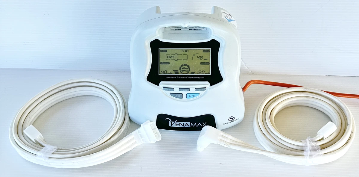
A schematic diagram of the typical intermittent pneumatic compression
4.9
(760)
Write Review
More
$ 24.00
In stock
Description

Advancements in compressed air engine technology and power system

Formation and Transport of Lymph
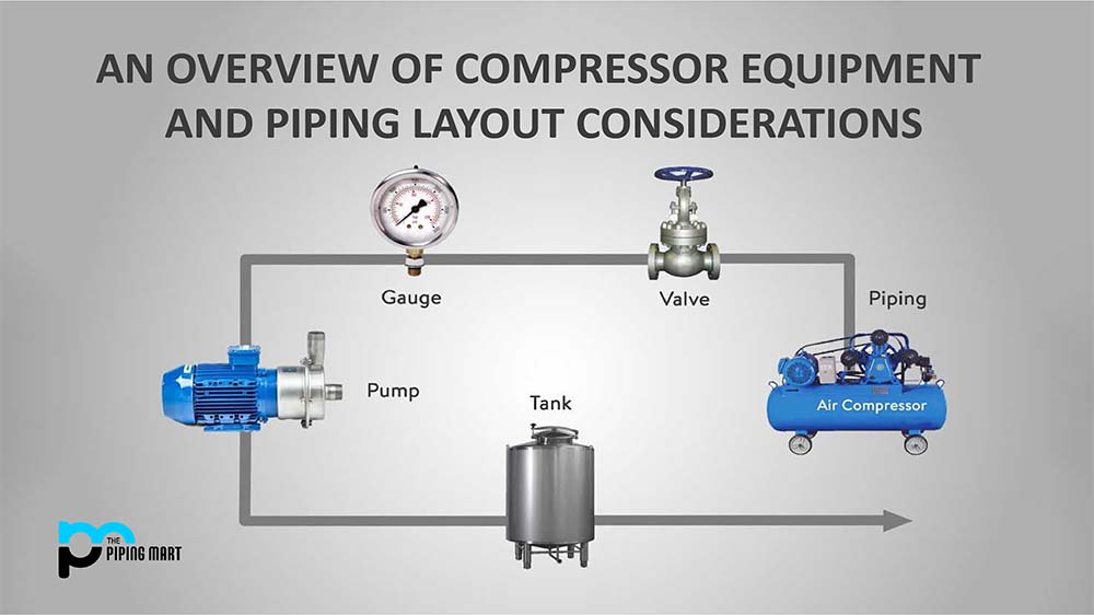
An overview of Compressor Equipment and Piping Layout
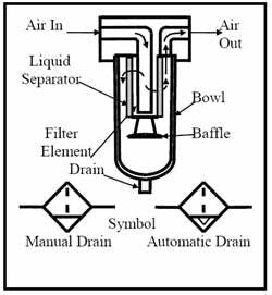
CHAPTER 7: Air and Hydraulic Filters, Air Dryers and Lubricators

Exergy analysis of pressure reduction, back pressure and

Sensors, Free Full-Text
Diesel engine, Definition, Development, Types, & Facts

Schematic representation of the pathophysiology of DVT. DVT mainly

Rong LIU, PhD

PDF) Dynamic Interface Pressure Monitoring System for the
Related products